Failover clusters in Windows Server 2012 provide a high-availability solution for many server roles and applications.
By implementing failover clusters, you can maintain application or
service availability if one or more computers in the failover cluster
fails.
There are a lot of information that you can digest on the Failover Clustering, for more information please log in to :
http://technet.microsoft.com/en-us/library/hh831579.aspx
For this Failover Clustering demo, i will be using 4 VM’s, which is
domain controller and 3 member server. Please refer to the screenshot :
 1st : our 1st step is to configure a Failover Cluster, which
is in this step i will connect a cluster nodes to the iSCSI targets…
Scenario for this demo is very simple :
1st : our 1st step is to configure a Failover Cluster, which
is in this step i will connect a cluster nodes to the iSCSI targets…
Scenario for this demo is very simple :
“Your organization has important applications and services that the company wants to make highly available.
Some of these services cannot be made redundant by using NLB, so you decide to implement failover clustering.
Because iSCSI storage is already in-place, you decide to use the iSCSI storage for failover clustering.
First, you will implement the core components for failover clustering and validate the cluster, and then you will
create the failover cluster.”
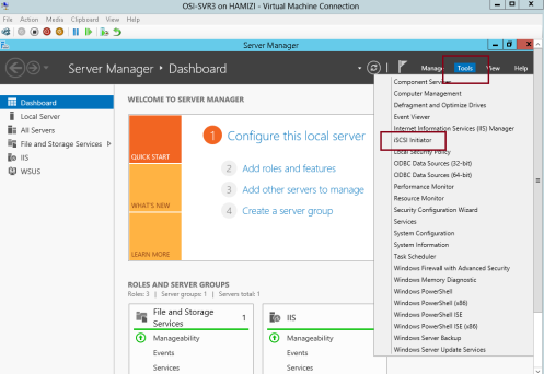
1 – For this configuration i will be using my OSI-SVR3 member
server, on OSI-SVR3, open Server Manager, click Tools, and then click
the iSCSI Initiator…
2 – In the Microsoft iSCSI interface, just click Yes…

3 – on the iSCSI initiator Properties interface, click the Discovery tab and then click Discover Portal…
** Internet SCSI (iSCSI) initiator –> to established a connection with an iSCSI target

4 – In the IP address or DNS name box, type 172.16.0.21, and then click OK…
172.16.0.21 – OSi-SVR1 server

5 – Next, click the Targets tab, and click Refresh…
** In the Targets list, select
iqn.1991-05…., and then click Connect…

6 – then cllick Add this connection to the list of Favorite Targets, and then click OK two times…
 ** Please repeat the step 1 – 6 on your SVR4 server…
7 – Switch to SVR3 and open Computer Management and make sure that
you have few disk already attach to your Server to stimulate this demo,
for this demo i have 3 VHD that i attach previously on the SVr3 server,
all 3 disk having 30GB space each, you may choose your own space.

8 – Switch to SVR4 and please make sure also that you have the same disk configuration…
** make sure that all the disk is online (Right-click Disk 1, and then click Online)….
 2nd : Let install the failover clustering feature on our SVR3 server….
1 – Open Server Manager and continue with add roles & feature
until you reach Select features interface, then click Failover
Clustering and continue with installation…

2 – next on the Confirm installation selections interface, click Install…

3 – Once installation complete, click Close…
 ** Repeat steps 1 – 3 on SVR4 server…
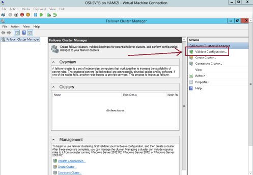
4 – Now we need to validate the both servers for failover clustering, on the SVR3 server open Failover Cluster Manager…

5 – On the right pane of Failover Cluster Manager, click Validate Configuration…
6 – In the Validate a Configuration Wizard interface, click Next…

7 – On the Select Servers or a cluster interface, please add our SVR3 & SVR4 and then click Next…

8 – On the Testing options interface, click Run all tests (recommended) and then click Next…

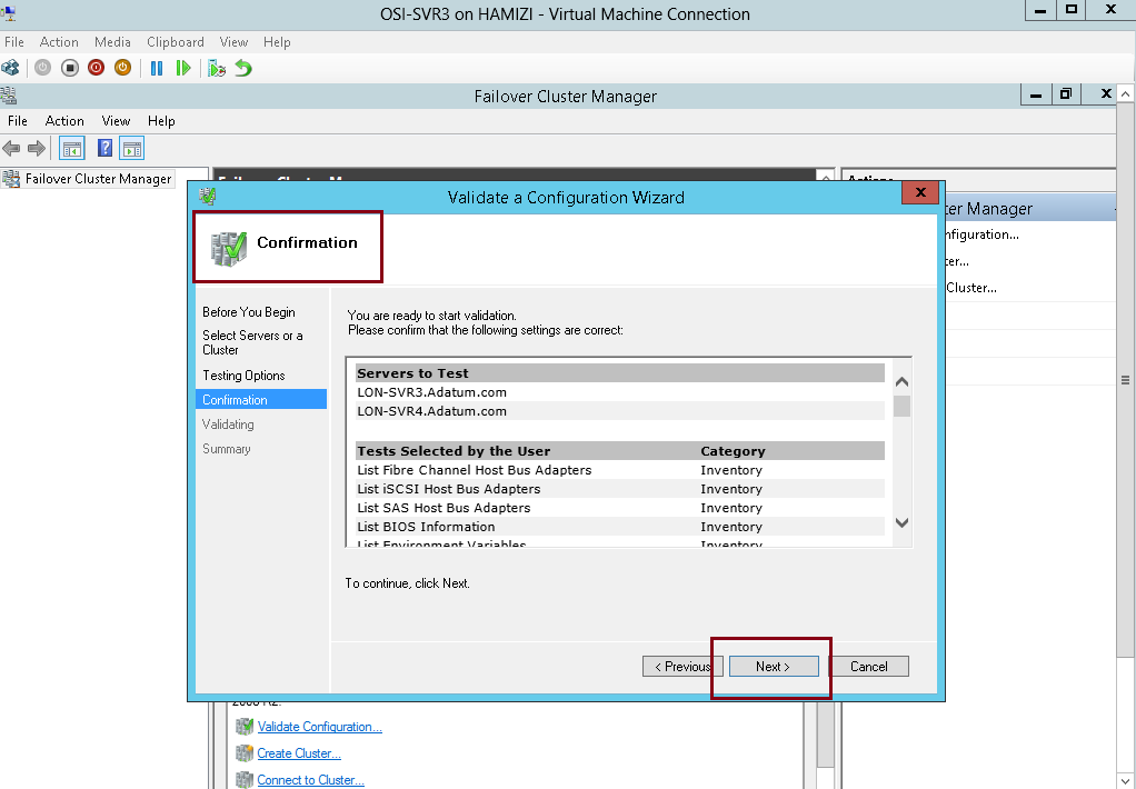
9 – On the Confirmation interface, click Next…

10 – This process might take up to 5 – 10 minutes…

11 – Once the validation tests to finish, on the Summary page, click View Report…

12 – Just verify that all tests completed…
 3rd : Our next step is to create the failover cluster…
1 – in the Failover Cluster Manager, click Create Cluster….

2 – then click Next…

3 – On the Select Servers interface, make sure you add SVR3 & SVR4 in the selected servers and then click Next…

4 – In Access Point for Administering the Cluster interface, in the Cluster Name box, type OSICluster1.
** Under Address, type 172.16.0.125, and then click Next.

5 – In the Confirmation box, verify the information, and then click Next…

6 – On the Summary interface, click Finish…
 4th : Configuring CSV
” Cluster Shared Volumes (CSV) enable multiple nodes in a failover
cluster to simultaneously have read-write access to the same LUN (disk)
that is provisioned as an NTFS volume.
With CSV, clustered roles can fail over quickly from one node to
another node without requiring a change in drive ownership, or
dismounting and remounting a volume.
CSV also help simplify the management of a potentially large number of LUNs in a failover cluster.”
1 – On SVR3 server, in the Failover Cluster Manager console, expand cluster1.
Adatum.com, expand Storage, and then click Disks.
** locate a disk that is assigned to Available Storage. You can see this in the Assigned To column.
** Right-click that disk, and then click Add to Cluster Shared Volumes.
** Verify that the disk is assigned to Cluster Shared Volume…
 5th : Our next step is to deploy and configure Highly Available File Server…
1 – On the SVR4 server, open Server Manager, click add roles &
features and continue to Select server roles and then select File
Server, then click Next 2 times…

2 – On the Confirmation interface, click Install…

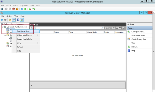
3 – Next, switch back to SVR3 server, in the Failover Cluster Manager, expand Cluster1.
adatum.com, right-click Roles, and then select Configure Role…
4 – click Next…

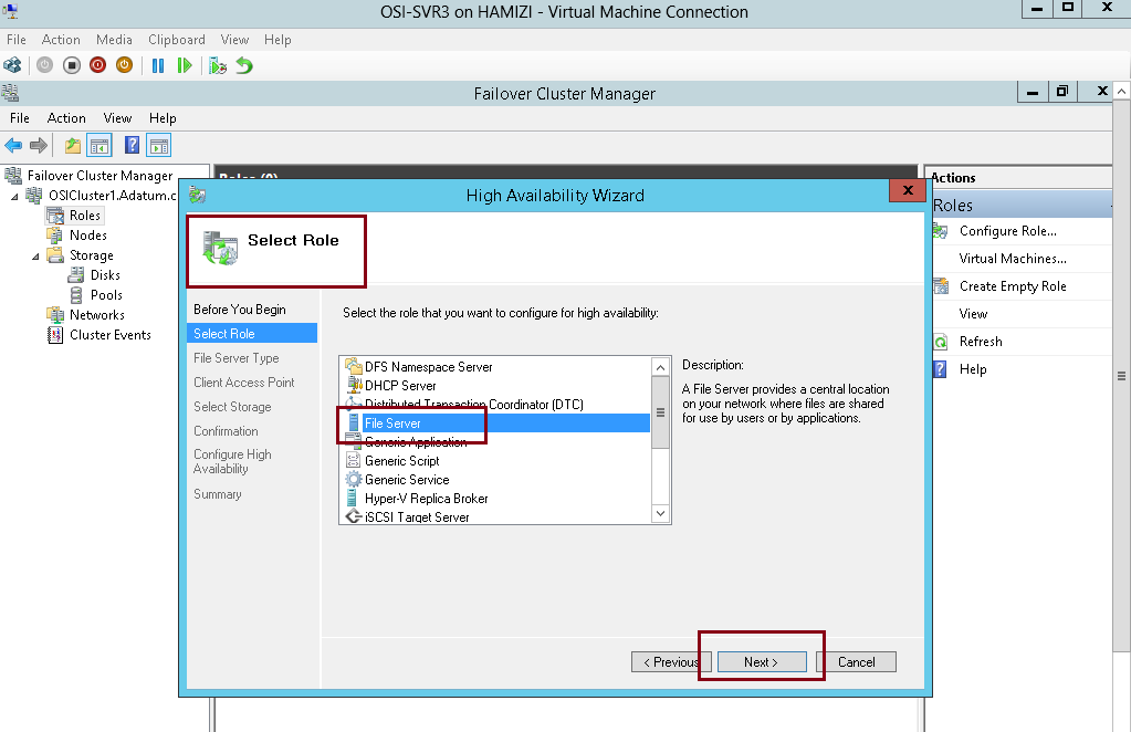
5 – On the Select Role interface, select File Server, and then click Next….

6 – On the File Server Type interface, click File Server for general use, and then click Next…

7 – On the Client Access Point interface, in the Name box, type
OSI-FS, in the Address box, type 172.16.0.130, and then click Next…

8 – On the Select Storage interface, select the Cluster Disk 3 check box, and then click Next…

9 – On the Confirmation interface, click Next…

10 – click Finish…
 6th : Next we going to add a shared folder to a highly available File Server…
1 – Switch to SVR4 server and open Failover Cluster Manager…
** Expand Cluster1.
Adatum.com, and then click Roles.
** Right-click OSI-FS, and then select Add File Share…

2 – In the Select the profile for this share interface, click SMB Share – Quick, and then click Next…

3 – On the Select the server and the path for this share interface, verify the server & Volume to share and then click Next…

4 – On the Specify share name interface, in the Share name box, type OSI-Docs, and then click Next…

5 – On the Configure share settings interface, do not make any changes, and then click Next…

6 – On the Specify permissions to control access interface, click Next…

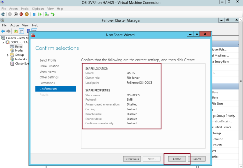
7 – On the Confirm selections interface, click Create…
8 – On the View results interface, click Close…

9 – Next we need to configure
failover and failback settings, on the Failover Cluster Manager, click Roles, right-click OSI-FS, and then click Properties…
“** Failover transfers the responsibility of providing access to
resources in a cluster from one node to another. Failover can occur when
an administrator intentionally moves resources to another node
for maintenance, or when unplanned downtime of one node happens because
of hardware failure or other reasons. In addition, service failure on
an active node can initiate failover to another node.”
“** The Cluster service can failback instances that were originally
hosted on the offline node after the offline node becomes active again.
When the Cluster service fails back an instance, it follows the
same procedures that it performs during failover. That is, the Cluster
service takes all the resources in the instance offline, moves the
instance, and then brings all the resources in the instance back
online.”

10 – Click the Failover tab and then click Allow failback…
** Click Failback between, and set values to 3 and 4 hours.

11 – Next, click the General tab, then select SVR3 and SVR4 as preferred owners and make sure you move SVR4 up, then click OK…
 7th : Now we have to validate / verify the Deployment of our High Availability File Server
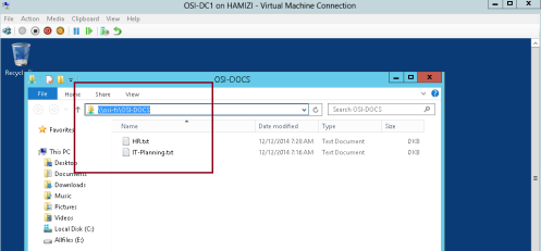
1 – Switch to DC01 server (Domain Server), try access to \\osi-fs\osi-docs…
** Verify that you can access the location and that you can open the osi-docs folder…

2 – To verify you can create a any text document inside this folder…

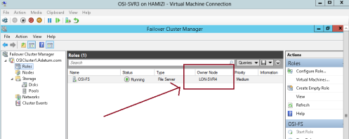
3 – Next, switch back to SVR3 server and open the Failover Cluster Manager.
** Expand Cluster1.
adatum.com, and then click Roles. Note the current owner of OSI-FS (SVR3)
** Right-click OSI-FS, click Move, and then click Select Node…

4 – In the Move Clustered Role box, select the cluster node (it will be either SVR3 or SVR4), and then click OK…

5 – Verify that SVR4 has moved to a new owner…
** I do recommend that you switch back to DC1 server and verify that you can still access the \\osi-fs\osi-docs…
6 – Next, in the Failover Cluster Manager, right-click the node (I
choose SVR4) , select More Actions, and then click Stop Cluster Service…

7 – Verify that SVR4 now is down…
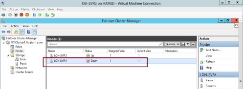
8 – Verify also OSI-FS has moved to another node which is SVR3…
** ** I do recommend that you switch back to DC1 server again and verify that you can still access the \\osi-fs\osi-docs…

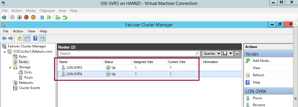
9 – switch back to SVR3 server and on the Failover Cluster Manager,
click Nodes. Right-click the stopped node which the SVR4, select More
Actions, and then click Start Cluster Service…
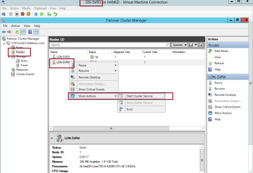
10 – Verify all nodes status now up…

11 – Next, expand Storage, and then click Disks.
In the center pane, right-click the disk that is assigned to Disk Witness in Quorum then click Take Offline…
“** Quorum is the number of elements that must be online for a
cluster to continue running. In effect, each element can cast one vote
to determine whether the cluster continues to run. Each cluster node is
an element that has one vote. In case there is an even number of nodes,
then an additional element, which is known as a witness, is
assigned to the cluster. The witness element can be either a disk or a
file share. Each voting element contains a copy of the
cluster configuration; and the Cluster service works to keep all copies
synchronized at all times.”

12 – then click Yes…

13 – Switch to DC1 server and verify that you can still access the \\osi-fs\osi-docs location. By doing this, you
verified that the cluster is still running, even if the witness disk is offline…
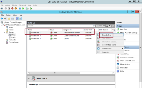
14 – Now switch back to SVr3 server, in Failover Cluster Manager,
expand Storage, click Disks, right-click the disk that is in Offline
status, and then click Bring Online…
15 – Next, right-click Cluster1.
Adatum.com, select More Actions, and then click Configure Cluster Quorum Settings…

16 – click Next…

17 – On the Select Quorum Configuration Option interface, click Advanced quorum configuration, and then click Next…

18 – On the Select Voting Configuration interface,Do not make any changes, and then click Next…

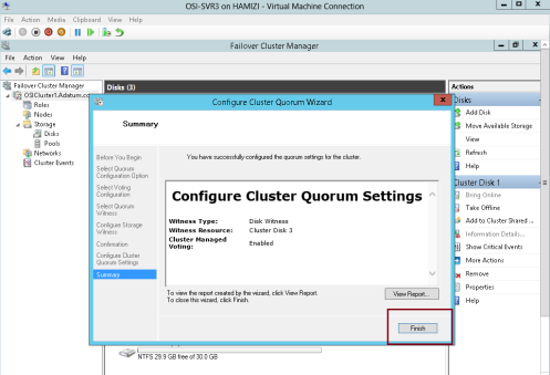
19 – On the Select Quorum Witness interface, select Configure a disk witness and then click Next…

20 – On the Configure Storage Witness interface, select Cluster Disk 3, and then click Next…

21 – click Next…

22 – click Finish…
** we have succesfully tested the failover scenarios and next we going to configure CAU
 8th : Configure CAU – Cluster-Aware Updating
** Cluster-Aware Updating (CAU) is a technology in Windows Server
2012 that automatically updates cluster nodes with Windows Update
hotfix, by keeping the cluster online, and minimizing downtime.
** During an update procedure, CAU transparently takes each cluster
node offline, installs the updates and any dependent updates, and then
performs a restart if necessary. CAU then brings the node back online,
and moves to update the next node in a cluster.
1 – Before we proceed, please make sure that you have install Failover Clustering feature in DC1 Domain Server…
2 – Switch back to SVR3 & SVR4 server, and please verify also
that Inbound Rule for Remote Shutdown (RPC-EP-In) & Inbound Rule for
Remote Shutdown (TCP-In) rule is enabled…

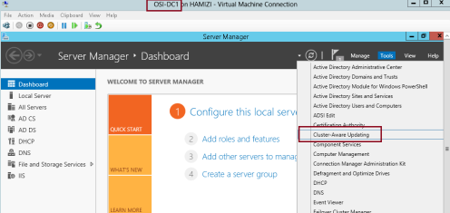
3 – let’s return to DC1 domain server and open Cluster-Aware Updating console…
4 – In the Cluster-Aware Updating interface, in the Connect to a
failover cluster drop-down list box, select OSICLUSTER1, and then click
Connect…

5 – In the Cluster Actions pane, click Preview updates for this cluster…

6 – In the OSICluster1-Preview Updates interface, click Generate Update Preview List…

7 – After few minutes, updates will display in the list and then click Close…

8 – still on the DC1 server, now we need to update the failover cluster and configure the self-updating…
** in the Cluster-Aware Updating console, click Apply updates to this cluster…

9 – On the Getting Started interface, click Next…

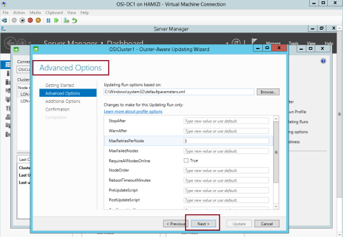
10 – On the Advanced options interface, review the options for updating, and then click Next…
11 – On the Additional Update Options interface, click Next…

12 – On the Confirmation interface, click Update, and then click Close…

13 – In the Cluster nodes pane, you can review the progress of the updating process…
** Please take note that 1 node of the cluster is in a waiting state, and the other node is restarting after it is updated.
** Wait until the process is finished and both nodes will restarted automatically.

14 – The process is finished when both nodes show Succeeded…
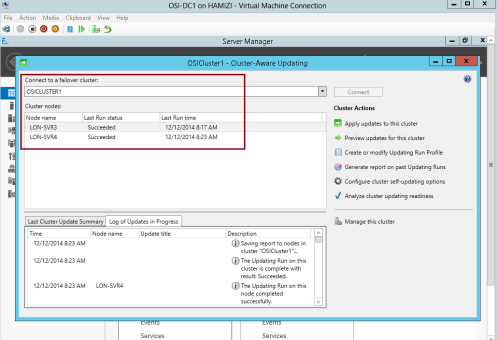
15 – Once the SVR3 restarted, log in as administrator and open Cluster-Aware Updating…
** In the Cluster-Aware Updating box, in the Connect to a failover
cluster drop-down list box, select OSICLUSTER1. Click Connect….

16 – Click the Configure cluster self-updating options in the Cluster Actions pane…

17 – On the Getting Started interface, click Next…

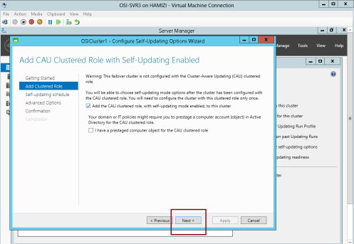
18 – On the Add CAU Clustered Role with Self-Updating Enabled
interface, click Add the CAU clustered role, with self-updating mode
enabled, to this cluster, and then click Next…
19 – On the Specify self-updating schedule page,configure your own schedule and then click Next…

20 – On the Advanced Options interface, click Next…

21 – On the Additional Update Options interface, click Next….

22 – On the Confirmation interface, click Apply…

23 – After the clustered role is added successfully, click Close and we have successfully configured CAU.

That’s all for now.. i know its a long step, but i hope for those who
taking MCSA exam code 70-412, you should do a lot of exercises on the
Failover Cluster.
Most IMP: Quorum part is the most tricky configuration in Windows Failover Cluster Server. Try to have the best possible understanding of it in order to avoid the confusion at the time of troubleshooting WFSC issues or while creating/Validating the WFCS